
Beta Transus: Managing Adiabatic Heating During α+β Titanium Forging
The interactive simulator below lets you visualize the heat gain during forging of a typical Ti-6Al-4V forging. By adjusting the 3 critical levers (Strain Rate, Deformation Amount, and Furnace Setpoint), you can see exactly how a “safe” process can slide into the Beta Transus danger zone.
Play with the tool to see the physics in action, then read my full post below for a deep dive into how Adiabatic Heating during forging works!
As forging engineers, we spend half our time coming up with cool processes and the other half explaining how we promise it will make good parts! One of the biggest forge process risk area in aerospace, medical, and automotive forgings is the Beta Transus Temperature of α+β Titanium alloys.
Beta Transus Temperature - the temperature at which titanium alloys completely transform from a two-phase alpha+beta (α+β) microstructure to a single-phase beta (β) microstructure upon heating.
We want to maximize die life and minimize flow stress, while proving we'll stay below the beta transus to meet metallurgical and mechanical specifications.
The challenge is that heat doesn't just come from the furnace. It comes from the process itself. This is “adiabatic heating”, and in α+β Titanium alloys like Ti-6Al-4V and Ti-6Al-7Nb, it is the invisible variable that separates a ductile forging from scrap metal.
1. Fundamentals of Titanium Metallurgy
To understand the forging risk, you have tounderstand titanium’s unique structure. Titanium is “allotropic”, meaning its microstructure can be in 2 different arrangements depending on the temperature.
Structure & Stability
Pure titanium exists as a Hexagonal Close Packed (HCP) structure, known as the α-phase, at room temperature. This phase is stable up to around 1620°F. Above this temperature, the it rearranges into a Body Centered Cubic (BCC) structure, known as the β-phase, which is stable all they way up to the melting point.
Mechanical Property Differences
α-phase (Alpha/HCP): Alpha phase structure provides the high strength and ductility required to meet mechanical testing requirements, but lacks fracture toughness.
β-phase (Beta/BCC): The β-phase much more ductile and formable at high temperatures. This is why we heat Titanium to forge it, to access these slip systems and lower the flow stress. But, at room temperature, it cools to form a “Basketweave” or “Widmanstätten” structure with the leftover Alpha grains which is brittle and often fails tensile and ductility requirements.
The Alpha + Beta Advantage
Alloys like Ti-6Al-4V (Aerospace/Medical/Automotive) and Ti-6Al-7Nb (Medical) use added Aluminum to stabilize the Alpha phase and Vanadium/Niobium to stabilize the Beta phase. Best of both worlds! Forging these mixed "Alpha + Beta" alloys gives us the forgeability of Beta while offering added strength, ductility, and fatigue resistance. But, the Beta Transus temperature is a hard ceiling that turns this mixture into a brittle “basketweave” or “Widmanstätten” structure that destroys ductility.
2. The Beta Transus Threshold
The Beta Transus is the temperature ceiling where the Alpha phase completely disappears, transforming 100% of the material into Beta phase. For standard pure Ti this is low (~1625°F), but Ti-6Al-4V is typically 1790-1840°F. Ti-6Al-7Nb can be as high as 1860°F.
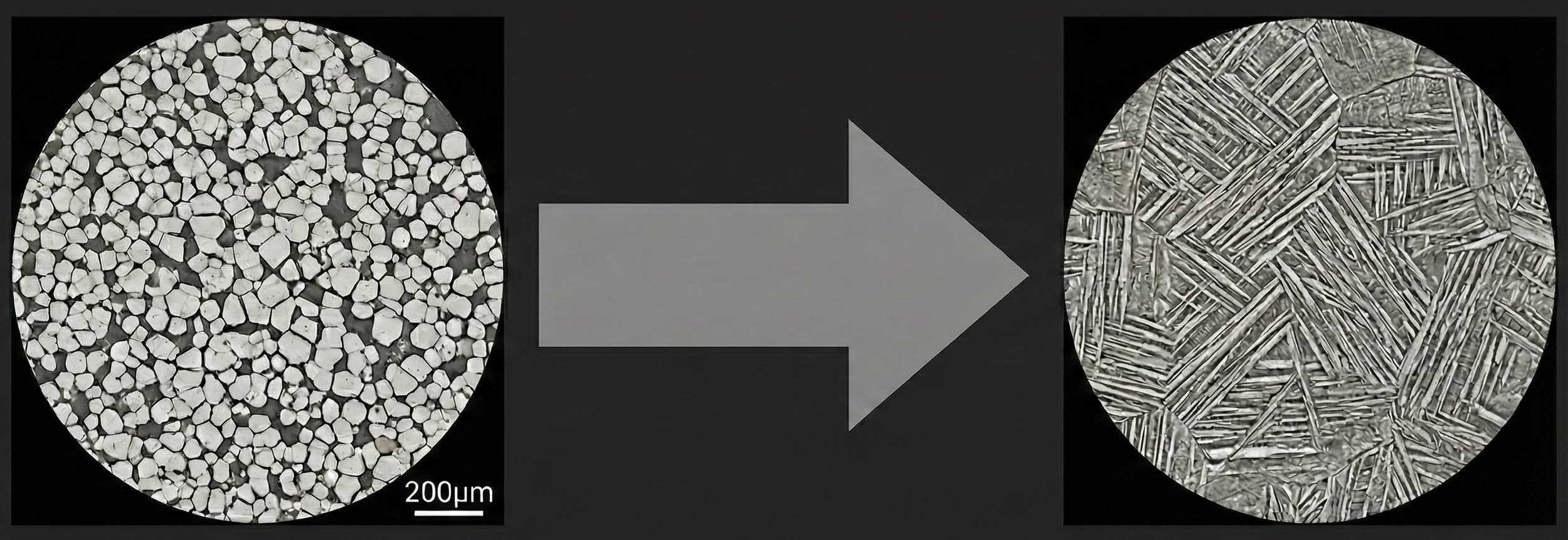
Figure 1: As temperature approaches the Transus (1823°F), ductile Alpha vanishes.
As the core of our forging approaches this beta transus temperature, the mixture gradually transforms into more beta-phase than alpha-phase. Upon cooling, instead of returning to a fine, equiaxed mixture of both, it forms coarse plates of lamellar alpha and needle-like beta. This structure acts like a brittle ceramic plate with high fracture toughness but very low ductility.
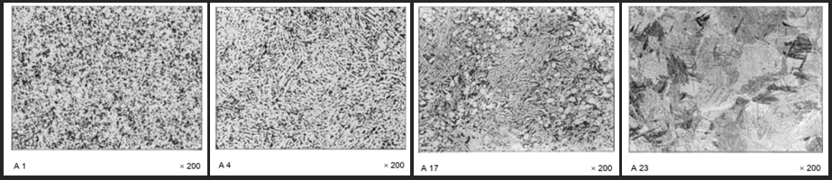
ISO20160 α+β Phase Distribution Analysis Grades A1, A4, A17, and A23
3. The Three Levers of Heat Generation
When work is done, energy must be conserved. That’s why a paperclip gets hot when you bend it back and forth. When a forge press deforms a billet, it performs tons (no pun intended) of mechanical work. Around 90% of that work is instantly converted into heat within the material itself.
Distribution of strain, temperature after forging and time above β transus for Ø45 × 67.5 mm billet forged at 950 °C.
Kulakov, Mykola & da Silva, Laurie & Andreu, Aurik. (2020). Effect of adiabatic heating on microstructure evolution in Ti-6Al-4V during high strain rate forging. MATEC Web of Conferences. 321. 12003. 10.1051/matecconf/202032112003.
How much heat is generated seems like a mystery and you just have to hit some parts and see what happens, but the temperature rise (ΔT) actually follows this basic relationship:
ΔT = (0.90 / Density x Specific Heat) x Work Being Done
For many materials (e.g. steels, aluminum, brass), this equation is toned down by including Thermal Conductivity (k), but Titanium is a terrible conductor of heat. Forging happens so fast that Titanium alloys retain almost all the heat inside the material itself, causing adiabatic heat rise.
To control this adiabatic heat rise during forging, the die designer has 3 specific levers balance:
Lever 1: Strain Rate (Ram Speed)
Titanium is highly strain-rate sensitive. The faster you deform it, the harder it fights back (Flow Stress increases). This creates a phenomenon known as Flow Softening. The chart below shows the interaction between the amount of heat generated as work being done (Strain) rises at 2 different ram speeds (Strain Rate).
The white lines are flow stress and heat rise at a low strain rate (slow hydraulic or isothermal press speed). You can see the flow stress stays even as the work being done increases because not much heat is created in the billet.
The yellow lines are stress and heat rise at a higher strain rate (mechanical or screw press). You can see the flow stress is much higher, plenty of heat is generated, and the flow stress lowers as the work being done generates heat and softens the material.
Note: Strain Rate doesn’t always follow Ram Speed. The material also accelerates when forced through tight die geometry (e.g. fins, ribs, or tight gaps). This volume-based flow speed can create spots of high strain rate even when the dies are moving slowly.
Lever 2: Total Strain (Deformation Amount)
Heat generation due to work being done is continuous. The more more work you do, the hotter it gets. The chart below shows the increase in Adiabatic Heat generation due to an increase of deformation at a given strain rate:
Doing too much work in one hit or having areas of the billet extremely deformed during forging creates loads of heat!
Lever 3: Initial Temperature (Thermal Safety Margin)
The final lever is your starting billet temperature. This acts as the floor of your process window, while the Beta Transus temperature acts as the ceiling. This chart shows the typical heat rise at different billet temperatures and how the safety margin decreases the hotter you go:
As you raise the furnace temperature (white line), the material gets softer and more forgeable, but this give you less room for doing more work or allowing fast ram speeds.
4. The Processing Window
Combining those 3 levers into 1 process design creates a complex problem for forging and die design engineers. We can’t just pick a single temperature for everything made with a certain material and hope for the best. We have to look at the interaction of those 3 levers and consider the amount of heat that may be generated and what mechanical/microstructural properties.
The chart below shows the “safe” zone and the “risk” zone where crossing the beta transus becomes a problem at different strain rates:
5. Comparison: Surface vs. Core
The most annoying part of adiabatic heating is that it is localized. Areas of higher Adiabatic Heat generation (more strain, higher strain rate, higher temp) will get closer to the Beta Transus. In the simple flattening example in the DEFORM image in section 3, the core is insulated and overheats quickly due to higher strain, while the surface is chilled by the dies and sees significantly less work being done. This results in varying Alpha + Beta mixes and huge mechanical property differences:
The areas forged closer to or above the Beta Transus will have slightly less strength and less ductility due to higher Beta-phase percentage.
These high Beta % forgings aren’t always “bad”. They have much higher fracture resistance and better creep resistance at higher temperatures.
If you thought this was cool, go back to the top of the page and play with the Interactive Simulator to visualize how this all works!
References:
Mostly CSV exports from DEFORM to build the various charts and many industry projects over the years. Plus, I just like to write nerd stuff!
DEFORM 3D (Scientific Forming Technologies Corporation) The industry standard FEM software used to calculate adiabatic heating and predict flow localization for various ram speeds, starting temperatures, and strain amounts.
Other sources used for sanity checks, specific values for building simulation setups, and lots of great reading you can find on Academia, Research Gate, and Springer:
Effect of adiabatic heating on microstructure evolution in Ti-6Al-4V during high strain rate forging Kulakov, Mykola & da Silva, Laurie & Andreu, Aurik. (2020). MATEC Web of Conferences.
Processing map for hot working of Ti–6Al–4V Seshacharyulu, T., et al. (2002). Materials Science and Engineering: A, 325(1-2), 112-123.
The effect of strain rate on flow stress and microstructure during hot working of Ti-6Al-4V Semiatin, S. L., et al. (1999). Materials Science and Engineering: A, 263(2), 257-271.
Influence of processing on microstructure and mechanical properties of (α+β) titanium alloys Lütjering, G. (1998). Materials Science and Engineering: A, 243(1-2), 32-45.
Low temperature forging of Ti-6Al-4V Shell, E. B., & Semiatin, S. L. (1999). Metallurgical and Materials Transactions A, 30, 3219–3229.
Flow softening mechanisms during hot working of Ti–6Al–4V Bruschi, S., et al. (2004). Materials Science and Engineering: A, 384(1-2), 279-284.
Adiabatic Shear Localization: Occurrence, Theories and Applications Bai, Y., & Dodd, B. (1992). Pergamon Press.
Flow Stress of Ti-6Al-4V during Hot Deformation: Decision Tree Modeling. Metals, Lim, S.-S., Lee, H.-J., & Song, S.-H. (2020).
Thermomechanical processing of beta titanium alloys—an overview Weiss, I., & Semiatin, S. L. (1998). Materials Science and Engineering: A, 243(1-2), 46-65.
Deformation and Fracture of Ti-6Al-4V at High Temperatures Semiatin, S. L., & Bieler, T. R. (2001). Acta Materialia, 49(19), 3965-3977.
Follow me on LinkedIn! Or hit me up with the form below: